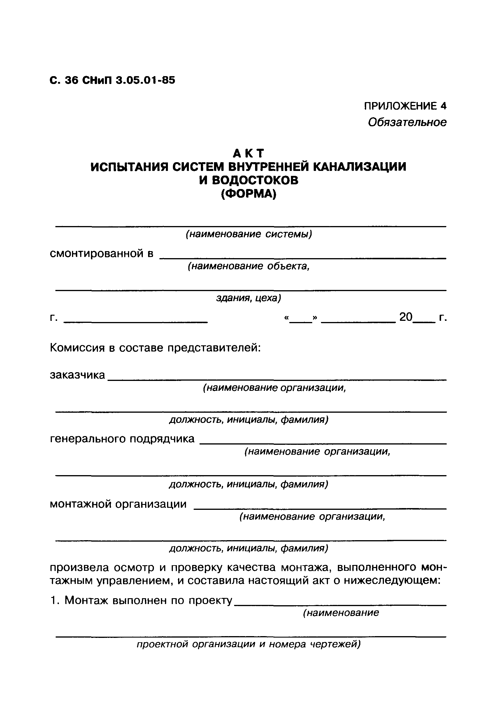
Protokol Aerodinamicheskih Ispitanij Ventilyacii Blank
Pharmacogenetics of Carboxylesterase 1 Katriina Tarkiainen ACADEMIC DISSERTATION To be presented, with the permission of the Faculty of Medicine of the University of Helsinki, for public examination in Lecture Hall 3 of Biomedicum Helsinki 1, Haartmaninkatu 8, on 9 June 2017, at 12 noon.
An unexpected borylation of organic halides with a silyborane in the presence of an alkoxy base has been observed. This formal nucleophilic boryl substitution can be applied to a broad range of substrates with high functional group compatibility. Even sterically hindered aryl bromides afforded the corresponding boryl compounds in high yields. Preliminary mechanistic studies indicated that this boryl substitution is promoted by neither transition-metal contamination nor a radical-mediated process.
Builders' notes for Cape Henry 21 sailboat DUDLEY DIX YACHT DESIGN Cape Cutter 19 & Cape Henry 21 Builders' Notes - Updated 15 November 2009 CAPE HENRY 21 PHOTOS These pages show a mixture of CC19 and CH21 photos. Construction of the two designs is almost identical, so builders of each design will benefit from photos of the other. 1 ~ DECK STRINGER END SUPPORTS The ends of the deck stringers must be supported where they run out against bulkheads 2 and B. This is most easily done by cutting U-shape brackets from 12mm plywood and bonding each to the bulkhead face to form a socket in which the stringer end can be bonded. Fit 22x22mm [7/8x7/8'] square cleats against the bulkheads between the stringers to form a landing for the plywood deck.
The diagram below shows how this works on bulkhead 2. The same principle applies at bulkhead B. Similar doublers can be used to house the ends of berth supports and other joinery frames where they terminate against bulkheads.
PDF – is a cross-platform extension, which is necessary for the visualization of printed materials in electronic form. PDF documents can exist separately from the OS or hardware tools with which they were developed. Octet-stream how to open. Files of this format do not have restrictions on the length, number of types and image options, as they allow you to embed various multimedia tools, scan-line and vector images. It is created by specialists from Adobe Systems using separate PostScript resources.
2 ~ TRANSOM RADIUS The intended transom radius is shown on the lines drawing. This is the curvature for the outside of the transom. The transom and its doublers must be laminated over a temporary wooden mould shaped to the curve of the inside of the transom doublers, ie the transom and doubler thicknesses must be subtracted from the radius shown when building the mould.
The internal cut-outs from the doublers should be fastened to the mould as well but not glued to the transom. These will support the transom across the cutouts and ensure a more uniform curvature when the transom is removed from the mould. There will be some springback (straightening) of the laminated transom/doubler structure. It can be held to the intended shape by screwing two temporary curved frames to the inside or outside. These can be removed when the transom is restained by the hull and cockpit 3 ~ BUILDERS' FORUM There is an active builders discussion forum on Yahoo groups for builders of the Cape Henry 21. The address is.
You will need to register with Yahoo Groups to enter the forum. The issues discussed will be useful to builders of plywood Cape Cutter 19s as well.
4 ~ BULKHEAD A CORRECTION We have found a small error in the shape of the bottom panel of Bulkhead A as shown on patterns and kits supplied prior to May 10th 2004. The diagram below shows how to correct the error by gluing a wedge of plywood or timber onto the edge of the bulkhead.
The wedge is 7mm thick at the backbone and tapers to 0mm at the chine. In the diagram below the red lines show the original shape of the bulkhead and the blue lines show what it must be changed to. The stringer slot must also be adjusted to the new surface. The backbone has extra width to allow for the changing bevel angle that must be planed to suit the twist of the bottom skin angle. Establish this angle by making a saw cut into the backbone as an extension of the bulkhead edge from both sides.
Cut the backbone down to the intersection of the two cuts made at each bulkhead and use them as a guide for trimming the backbone to width and angle. 5 ~ SPACERS TO CENTREPLATE SLOT Bill Empsall in NY has found that the centreplate case closes a bit under pressure from the bottom panels when these are being fitted.
He recommends that a couple of temporary spacers be fitted into the slot to keep it at the correct width until the epoxy fillets can be done. Thanks Bill, for that tip. 6 ~ DOUBLERS TO BACKBONE IN BOW The backbone needs to be locally increased in width at the U-bolt for the bobstay. Do this by adding extra layers of plywood between chine 1 and DWL in the same way as shown in 'Bow Section at Sheer' on the construction drawing. Some builders have reported too much flexibility in the backbone in the lower bow area when building.
This bends when applying pressure to it during fitting of the forward bottom panels. There are two possible ways to compensate for this during building. A) Clamp temporary stiffener/s to the backbone between A and 2 to hold it straight while fitting the bow bottom panels. B) Fit a permanent 10mm plywood doubler each side between Bulkheads A and 2.